
The development and application of reactive power compensation technology
author: admin
2022-08-19
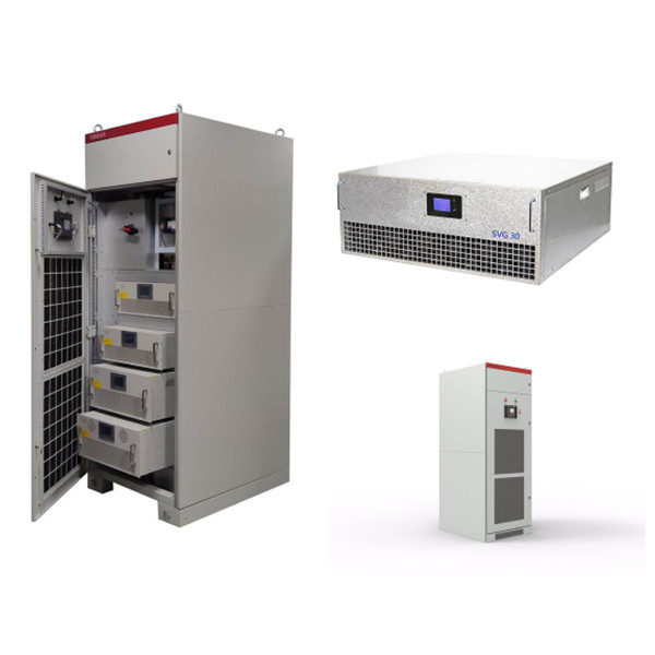
The development and application of reactive power compensation technology
Keywords: harmonic filter, reactive power compensation
The main content overview of this article:
1. Reactive power compensation technology and product efficiency
2. Harmony governance and reactive power compensation measures
3. Existing harmonic filters and reactive power compensation devices
4. Engineering application experience and precautions
Text
1. Reactive power compensation technology and product efficiency
1.1 Reactive power:
Reversible energy conversion is carried out between the power supply energy and the magnetic field energy in the inductive load coil or the electric field energy in the capacitive load capacitor, which occupies the grid capacity and is called reactive power.
1.2 Harmonics
Harmonics refer to currents or voltages of other frequencies that are not fundamental (50HZ China) in the power grid. Harmonics also belong to the reactive power category; source of harmonics: non-linear loads.
1.3 power factor
The ratio of active power to apparent power is called power factor
Power factor = displacement factor × distortion factor
Displacement factor: The cosine of the phase difference angle (load impedance angle) between the load current and the supply voltage.
Distortion factor: ratio of fundamental RMS to total RMS.
Sinusoidal condition: power factor = cosine of load impedance angle. Power factor is 1 for pure resistance.
Distortion condition: When the power supply is sinusoidal and the load current is distorted, even if the load is purely resistive, the power factor is ≠ 1. Such as: single-phase half-wave rectifier circuit with resistive load.
1.4 Negative impacts of reactive power
Reactive power has negative effects on voltage, current and line loss.
Voltage: Inductive reactive power makes the voltage drop, and capacitive reactive power makes the voltage rise.
Current: A reactive current component is generated, which increases the apparent current.
Line loss: reactive power increases the effective value of the current, resulting in increased losses in lines and transformers, and reduced transformer utilization.
1.5 Harm of Harmonics
Equipment (such as capacitors, lines, transformers, etc.) overcurrent;
Additional losses;
Metering errors;
Relay fault action;
Communication interference;
Power grid oscillation.
1.6 The role of harmonic elimination and reactive power compensation
The following effects on harmonic elimination and reactive power compensation:
Reduce apparent current and improve load capacity;
Reduce line loss and energy saving;
Improve phase imbalance;
Increase use ratio of transformers;
Stable grid voltage;
Improve power quality;
Make the power factor index up to standard and avoid fines from the authority.
2 2 Harmonic governance and reactive power compensation measures
2.1 2.1 Harmonic governance measures
a) LC filtering: single tuning, double tuning
Features: it is simple, low cost, and has large capacity and fundamental wave capacitive reactive power compensation capability. But it is easy to generate resonance, and the compensation circuit can only filter single harmonic.
b) Active Power Filter APF: Power Electronic Inverter Technology
Features: complex, high cost, small capacity, no danger of resonance, and can compensate various harmonics at the same time.
2.2 Modes of reactive power compensation
Under normal circumstances, loads are always inductive, so the required compensation current is capacitive;
a) Concentrated compensation mode: Generally, compensation is added at the position of high-voltage inlet lines, the compensation capacity is large, the number of compensating points is small, and the investment is small. The main solution of the power factor index is up to the standard; there is no improvement of the power factor and line loss in the user’s power network.
b) Local compensation mode: Compensation points are close to the load, the stand-alone compensation capacity is small, the required compensation points are large, and the investment is large.
2.3 Classification method of reactive power compensation devices
a) According to the motion of compensation device: rotation compensation, static compensation.
b) According to the response time division: static compensation, dynamic compensation.
Static var compensation device with dynamic compensation performance is the mainstream trend of nowadays reactive power compensation.
2.4 The advantages and disadvantages of various harmonic governance and reactive power compensation devices
a) Compensation of fixed capacitors –reactive power compensation
Advantages: simple, less investment;
Disadvantages: Compensation current cannot be adjusted with the load; compensation changes with the power supply voltage in the same direction, resonance is prone to occur.
b) Fixed LC filter -harmonic filter
It can filter out the harmonic resonance frequency and is capacitive to the fundamental wave, which belongs to static compensation.
c) Contactor switching capacitance compensation
The capacitors are divided into several groups, and the contactor is used to select and switch the corresponding capacitor group to realize the adjustment of the reactive power compensation amount.
Advantages: it can compensate reactive power with amount according to load need.
Disadvantages: It can cause current impact, delay relay process, noise suppression impact and series Anti-Surge Reactance.
The switching has 30S delay, it is static compensation, it is an obsolete product.
d) New generation of composite switching capacitance compensation (SLFK)
The composite switch replaces the contactor to switch the capacitor bank to realize the adjustment of reactive power compensation.
Objective: Using composite switch to control capacitor bank switching, stable operation.
Advantages: The current impact is reduced, no heat, no energy consumption, no noise, and it is static compensation.
/e) Thyristor Switching Capacitor Compensation (TSC)
The thyristor controls the switching of the capacitor bank to realize the adjustment of the reactive power compensation amount. Because the switching speed of the thyristor is fast (US grade), it is called "dynamic compensation".
Advantages: Quick dynamic adjustment compensation, small current impact, short-lapse, no noise.
Disadvantages: No harmonic suppression capacity, but the cost is expensive. It is dynamic compensation.
f) Thyristor Switching Filter Compensation (TSF)
The TSC compensation branch adopts LC single tuning (which needs to be designed according to the on-site working conditions) to become a TSF device, which can quickly adjust the magnitude of reactive power compensation, which is also called "dynamic compensation".
Advantages: Quick dynamic adjustment compensation, adapting to harmonic conditions, small current impact, short-lapse, no noise.
Disadvantages: cost is higher than TSC.
It is dynamic compensation, considering the harmonic factor and specially designed. The technology is mature and is being applied widely.
g) Active filter compensation device (SVG or APF)
Principle: SVG detects reactive power in real time (APF detects harmonics), and uses power electronic inverter technology to generate a current that is equal in size and opposite to the compensated object, canceling each other out, and the power factor can be close to 1.
Advantages: Dynamic response is faster, which can adapt to harmonic conditions. The compensation volume is not affected by the voltage of the power supply, no resonance hazards, no noise, and small footprint.
Disadvantages: high cost, large self-loss.
It is a dynamic compensation, and it will take time to promote the application.
h) TCR type SVC device: TCR + FC
Principle: The thyristor controllable reactor cooperates with the fixed capacitor (actually usually 5, 7, 11, 13, etc. filters), and uses the conduction angle of the thyristor to control the reactance of the reactor to achieve rapid dynamic adjustment of reactive power.
Advantages: smooth and stepless, dynamic response fast, it can adapt to harmonic conditions.
Disadvantages: The device produces harmonics itself.
This product is generally used for dynamic compensation of 10KV and 35KV high-voltage systems, and has been popularized and applied in China.
3. Mainstream filter compensation device in the market
3.1 Harmonics Compensation
a) LC filtering device -mainly uses single tuning and double-tuning, and it can compensate for high and low voltage systems.
b) Active harmonic filter –There are more and more applications.
3.2 Reactive power Compensation
a) Reactive power compensation - mainly capacitor compensation (TSC, TSF), few SVG.
b) compensation method -Static compensation is mainstream, TCR is gradually promoted, few STATCOM applications.
3.3 The technical solution of the existing market TSC device
Detection method: power factor, reactive power, reactive current detection
Switching control: cycle, coding, computer real-time calculation, (response time can reach within 40MS)
Switching switch: composite switch (not dynamic compensation in principle), solid state relay, double silicon anti-parallel, one silicon one diode
Operation mode: three-phase common compensation, separate-phase compensation
Compensation Insertion: Feedforward, Feedback
Operation mode: zero-crossing switching, capacitor pre-charging
Current Shock: It can realize switching without transient process.
Fault-tolerant operation: the faulty branch exits, and the normal branch runs.
Protection plan: short circuit, overcurrent, crystal tube failure, ultra -temperature, under pressure, over pressure, etc.
Recommended devices:
Detection method: reactive current detection
Switching switch: double silicon in parallel, or one silicon and one diode
Response time: It should be able to reach 40ms to 100ms
Impact current: as small as possible
Pay attention:
Under the condition that the system contains more harmonics, special attention should be paid to the anti-harmonic capability of the TSC device. The capacitance of the compensation branch of the TSC device has an amplifying effect on harmonics. When the harmonic content is large, the TSF device should be selected; the compensation branch of the TSF device adopts an LC filter, which has a certain harmonic absorption capacity, but the LC parameter design must be adapted to the on-site harmonic characteristics. The switching of the compensation branch of the TSF device needs to be controlled according to special requirements to prevent oscillation; when designing, attention should be paid to the influence of harmonics on the capacitor voltage and inductor current of the compensation branch of the TSF device. Filter cabinets for TSF installations generally require special design.
3.4 The development trend of dynamic reactive power compensation
a) Features of capacitor compensation solution:
Advantages: simple, reliable, cheap, small self-loss;
Disadvantages: The compensation volume is affected by the voltage of the power supply. It is dangerous to cause resonate, which is likely to amplify harmonics and occupy large area.
b) Static var generator SVG
Advantages: good compensation performance, not affected by power voltage, no resonance risk, small land, no harmonic release
Disadvantages: high cost, large self-loss, small compensation capacity, small compensation capacity,
SVG device is the development trend of reactive power compensation in the future.
4 Engineering application experience and precautions
4.1 Technical issues that occur in the application of reactive power compensation engineering
Capacitors are damaged in large quantities;
The compensation quantity is attenuation quickly;
Under-compensation and over-compensation occur frequently;
Oscillation occurs when the equipment is put into operation;
The compensation device has no noise in operation;
Electric fire and other malignant incidents occur.
4.2 Project Precautions
Concentrated compensation and local compensation optimization combination;
Fully understand the working conditions, power quality, and compensation capacity of compensation objects;
According to the compensation object, select the appropriate compensation device;
Appropriate engineering design.
4.3 Compensation method and its layout
According to the distribution of the system load, a reasonable selection of centralized compensation or locally compensation.
Selection principle:
Use local compensation for loads with high consumption of reactive power consumption to avoid large line loss.
For scattered small electricity loads, centralized compensation is selected, which is more economical.
4.4 Selection of compensation device
The TSC device or TSF device should be reasonably selected according to the harmonic content of the system.
Selection principle:
For systems with small harmonic content, choose TSC devices can save investment input;
For systems with large harmonic content, TSF devices should be considered to prevent harmonic enlargement and compensation capacitor overload damage.
4.5 Design principles of compensation device capacity
It can be fully compensated when full load, and no compensation occurs during empty loads.
4.6 High voltage reactive power compensation device
For the high -voltage system, according to the characteristics of the high -voltage system load, there are still two different methods of static compensation and dynamic compensation in China.
a) Static compensation method:
For cases where the load changes are not frequent or the fluctuations are not large, static compensation can be selected, such as: LC filter, vacuum contactor (circuit breaker) to switch capacitor (filter), etc.
Pay attention to prevent the influence of network voltage rise caused by excessive reactive power compensation.
b) Dynamic compensation method:
For rapid changes in loads, dynamic compensation should be selected, such as: TCR, Statcom, low -supplement high and other solutions:
TCR: Many domestic companies have produced such products, which are mostly used in the compensation of electric arc furnaces;
TSC: It is not popular at home, and there are a small amount of applications abroad;
STATCOM: Mainly large -scale engineering applications for transmission systems;
Low compensates high: no technical obstacles, cost factors.
Keywords: harmonic filter, reactive power compensation
The main content overview of this article:
1. Reactive power compensation technology and product efficiency
2. Harmony governance and reactive power compensation measures
3. Existing harmonic filters and reactive power compensation devices
4. Engineering application experience and precautions
Text
1. Reactive power compensation technology and product efficiency
1.1 Reactive power:
Reversible energy conversion is carried out between the power supply energy and the magnetic field energy in the inductive load coil or the electric field energy in the capacitive load capacitor, which occupies the grid capacity and is called reactive power.
1.2 Harmonics
Harmonics refer to currents or voltages of other frequencies that are not fundamental (50HZ China) in the power grid. Harmonics also belong to the reactive power category; source of harmonics: non-linear loads.
1.3 power factor
The ratio of active power to apparent power is called power factor
Power factor = displacement factor × distortion factor
Displacement factor: The cosine of the phase difference angle (load impedance angle) between the load current and the supply voltage.
Distortion factor: ratio of fundamental RMS to total RMS.
Sinusoidal condition: power factor = cosine of load impedance angle. Power factor is 1 for pure resistance.
Distortion condition: When the power supply is sinusoidal and the load current is distorted, even if the load is purely resistive, the power factor is ≠ 1. Such as: single-phase half-wave rectifier circuit with resistive load.
1.4 Negative impacts of reactive power
Reactive power has negative effects on voltage, current and line loss.
Voltage: Inductive reactive power makes the voltage drop, and capacitive reactive power makes the voltage rise.
Current: A reactive current component is generated, which increases the apparent current.
Line loss: reactive power increases the effective value of the current, resulting in increased losses in lines and transformers, and reduced transformer utilization.
1.5 Harm of Harmonics
Equipment (such as capacitors, lines, transformers, etc.) overcurrent;
Additional losses;
Metering errors;
Relay fault action;
Communication interference;
Power grid oscillation.
1.6 The role of harmonic elimination and reactive power compensation
The following effects on harmonic elimination and reactive power compensation:
Reduce apparent current and improve load capacity;
Reduce line loss and energy saving;
Improve phase imbalance;
Increase use ratio of transformers;
Stable grid voltage;
Improve power quality;
Make the power factor index up to standard and avoid fines from the authority.
2 2 Harmonic governance and reactive power compensation measures
2.1 2.1 Harmonic governance measures
a) LC filtering: single tuning, double tuning
Features: it is simple, low cost, and has large capacity and fundamental wave capacitive reactive power compensation capability. But it is easy to generate resonance, and the compensation circuit can only filter single harmonic.
b) Active Power Filter APF: Power Electronic Inverter Technology
Features: complex, high cost, small capacity, no danger of resonance, and can compensate various harmonics at the same time.
2.2 Modes of reactive power compensation
Under normal circumstances, loads are always inductive, so the required compensation current is capacitive;
a) Concentrated compensation mode: Generally, compensation is added at the position of high-voltage inlet lines, the compensation capacity is large, the number of compensating points is small, and the investment is small. The main solution of the power factor index is up to the standard; there is no improvement of the power factor and line loss in the user’s power network.
b) Local compensation mode: Compensation points are close to the load, the stand-alone compensation capacity is small, the required compensation points are large, and the investment is large.
2.3 Classification method of reactive power compensation devices
a) According to the motion of compensation device: rotation compensation, static compensation.
b) According to the response time division: static compensation, dynamic compensation.
Static var compensation device with dynamic compensation performance is the mainstream trend of nowadays reactive power compensation.
2.4 The advantages and disadvantages of various harmonic governance and reactive power compensation devices
a) Compensation of fixed capacitors –reactive power compensation
Advantages: simple, less investment;
Disadvantages: Compensation current cannot be adjusted with the load; compensation changes with the power supply voltage in the same direction, resonance is prone to occur.
b) Fixed LC filter -harmonic filter
It can filter out the harmonic resonance frequency and is capacitive to the fundamental wave, which belongs to static compensation.
c) Contactor switching capacitance compensation
The capacitors are divided into several groups, and the contactor is used to select and switch the corresponding capacitor group to realize the adjustment of the reactive power compensation amount.
Advantages: it can compensate reactive power with amount according to load need.
Disadvantages: It can cause current impact, delay relay process, noise suppression impact and series Anti-Surge Reactance.
The switching has 30S delay, it is static compensation, it is an obsolete product.
d) New generation of composite switching capacitance compensation (SLFK)
The composite switch replaces the contactor to switch the capacitor bank to realize the adjustment of reactive power compensation.
Objective: Using composite switch to control capacitor bank switching, stable operation.
Advantages: The current impact is reduced, no heat, no energy consumption, no noise, and it is static compensation.
/e) Thyristor Switching Capacitor Compensation (TSC)
The thyristor controls the switching of the capacitor bank to realize the adjustment of the reactive power compensation amount. Because the switching speed of the thyristor is fast (US grade), it is called "dynamic compensation".
Advantages: Quick dynamic adjustment compensation, small current impact, short-lapse, no noise.
Disadvantages: No harmonic suppression capacity, but the cost is expensive. It is dynamic compensation.
f) Thyristor Switching Filter Compensation (TSF)
The TSC compensation branch adopts LC single tuning (which needs to be designed according to the on-site working conditions) to become a TSF device, which can quickly adjust the magnitude of reactive power compensation, which is also called "dynamic compensation".
Advantages: Quick dynamic adjustment compensation, adapting to harmonic conditions, small current impact, short-lapse, no noise.
Disadvantages: cost is higher than TSC.
It is dynamic compensation, considering the harmonic factor and specially designed. The technology is mature and is being applied widely.
g) Active filter compensation device (SVG or APF)
Principle: SVG detects reactive power in real time (APF detects harmonics), and uses power electronic inverter technology to generate a current that is equal in size and opposite to the compensated object, canceling each other out, and the power factor can be close to 1.
Advantages: Dynamic response is faster, which can adapt to harmonic conditions. The compensation volume is not affected by the voltage of the power supply, no resonance hazards, no noise, and small footprint.
Disadvantages: high cost, large self-loss.
It is a dynamic compensation, and it will take time to promote the application.
h) TCR type SVC device: TCR + FC
Principle: The thyristor controllable reactor cooperates with the fixed capacitor (actually usually 5, 7, 11, 13, etc. filters), and uses the conduction angle of the thyristor to control the reactance of the reactor to achieve rapid dynamic adjustment of reactive power.
Advantages: smooth and stepless, dynamic response fast, it can adapt to harmonic conditions.
Disadvantages: The device produces harmonics itself.
This product is generally used for dynamic compensation of 10KV and 35KV high-voltage systems, and has been popularized and applied in China.
3. Mainstream filter compensation device in the market
3.1 Harmonics Compensation
a) LC filtering device -mainly uses single tuning and double-tuning, and it can compensate for high and low voltage systems.
b) Active harmonic filter –There are more and more applications.
3.2 Reactive power Compensation
a) Reactive power compensation - mainly capacitor compensation (TSC, TSF), few SVG.
b) compensation method -Static compensation is mainstream, TCR is gradually promoted, few STATCOM applications.
3.3 The technical solution of the existing market TSC device
Detection method: power factor, reactive power, reactive current detection
Switching control: cycle, coding, computer real-time calculation, (response time can reach within 40MS)
Switching switch: composite switch (not dynamic compensation in principle), solid state relay, double silicon anti-parallel, one silicon one diode
Operation mode: three-phase common compensation, separate-phase compensation
Compensation Insertion: Feedforward, Feedback
Operation mode: zero-crossing switching, capacitor pre-charging
Current Shock: It can realize switching without transient process.
Fault-tolerant operation: the faulty branch exits, and the normal branch runs.
Protection plan: short circuit, overcurrent, crystal tube failure, ultra -temperature, under pressure, over pressure, etc.
Recommended devices:
Detection method: reactive current detection
Switching switch: double silicon in parallel, or one silicon and one diode
Response time: It should be able to reach 40ms to 100ms
Impact current: as small as possible
Pay attention:
Under the condition that the system contains more harmonics, special attention should be paid to the anti-harmonic capability of the TSC device. The capacitance of the compensation branch of the TSC device has an amplifying effect on harmonics. When the harmonic content is large, the TSF device should be selected; the compensation branch of the TSF device adopts an LC filter, which has a certain harmonic absorption capacity, but the LC parameter design must be adapted to the on-site harmonic characteristics. The switching of the compensation branch of the TSF device needs to be controlled according to special requirements to prevent oscillation; when designing, attention should be paid to the influence of harmonics on the capacitor voltage and inductor current of the compensation branch of the TSF device. Filter cabinets for TSF installations generally require special design.
3.4 The development trend of dynamic reactive power compensation
a) Features of capacitor compensation solution:
Advantages: simple, reliable, cheap, small self-loss;
Disadvantages: The compensation volume is affected by the voltage of the power supply. It is dangerous to cause resonate, which is likely to amplify harmonics and occupy large area.
b) Static var generator SVG
Advantages: good compensation performance, not affected by power voltage, no resonance risk, small land, no harmonic release
Disadvantages: high cost, large self-loss, small compensation capacity, small compensation capacity,
SVG device is the development trend of reactive power compensation in the future.
4 Engineering application experience and precautions
4.1 Technical issues that occur in the application of reactive power compensation engineering
Capacitors are damaged in large quantities;
The compensation quantity is attenuation quickly;
Under-compensation and over-compensation occur frequently;
Oscillation occurs when the equipment is put into operation;
The compensation device has no noise in operation;
Electric fire and other malignant incidents occur.
4.2 Project Precautions
Concentrated compensation and local compensation optimization combination;
Fully understand the working conditions, power quality, and compensation capacity of compensation objects;
According to the compensation object, select the appropriate compensation device;
Appropriate engineering design.
4.3 Compensation method and its layout
According to the distribution of the system load, a reasonable selection of centralized compensation or locally compensation.
Selection principle:
Use local compensation for loads with high consumption of reactive power consumption to avoid large line loss.
For scattered small electricity loads, centralized compensation is selected, which is more economical.
4.4 Selection of compensation device
The TSC device or TSF device should be reasonably selected according to the harmonic content of the system.
Selection principle:
For systems with small harmonic content, choose TSC devices can save investment input;
For systems with large harmonic content, TSF devices should be considered to prevent harmonic enlargement and compensation capacitor overload damage.
4.5 Design principles of compensation device capacity
It can be fully compensated when full load, and no compensation occurs during empty loads.
4.6 High voltage reactive power compensation device
For the high -voltage system, according to the characteristics of the high -voltage system load, there are still two different methods of static compensation and dynamic compensation in China.
a) Static compensation method:
For cases where the load changes are not frequent or the fluctuations are not large, static compensation can be selected, such as: LC filter, vacuum contactor (circuit breaker) to switch capacitor (filter), etc.
Pay attention to prevent the influence of network voltage rise caused by excessive reactive power compensation.
b) Dynamic compensation method:
For rapid changes in loads, dynamic compensation should be selected, such as: TCR, Statcom, low -supplement high and other solutions:
TCR: Many domestic companies have produced such products, which are mostly used in the compensation of electric arc furnaces;
TSC: It is not popular at home, and there are a small amount of applications abroad;
STATCOM: Mainly large -scale engineering applications for transmission systems;
Low compensates high: no technical obstacles, cost factors.

